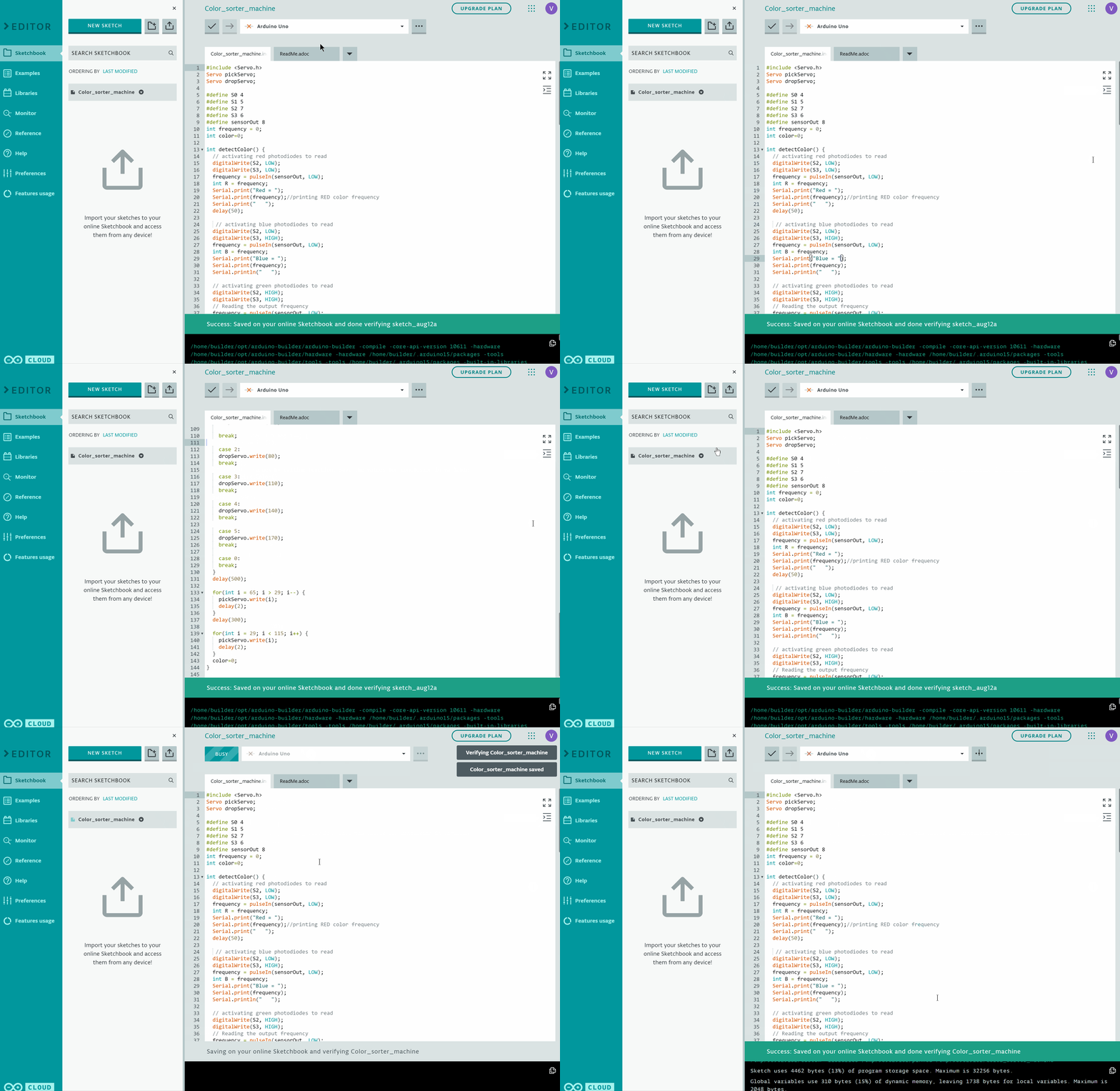
Code
At first we need to include servo.h library and define servo motors.
#include <Servo.h> //servo motor library
Servo pickServo; // create servo object to control a First servo
Servo dropServo; // create servo object to control a Second servo
Color sensor can work without library as there is only need of reading frequency from sensor pin to decide the color.
#define S1 6
#define S2 7
#define S3 8
#define sensorOut4
int frequency = 0;
int color=0;
Make the select pins as output as this will make the color photodiode high or low and take the Out pin of TCS230 as input. The OUT pin will provide frequency. Select the scaling of frequency as 20% initially.
pinMode(S1, OUTPUT);
pinMode(S2, OUTPUT);
pinMode(S3, OUTPUT);
pinMode(sensorOut, INPUT);
digitalWrite(S0, LOW);
digitalWrite(S1, HIGH);
The servo motors are connected at Pin 2 and 3 of Arduino. The pickup servo which will pickup the color balls is connected at Pin 2 and the drop servo which will drop the color balls according to the color is connected at Pin 3.
pickServo.attach(2);
dropServo.attach(3);
Initially the pick servo motor is set in the initially position which in this case is 115 degrees. It may differ and can be customized accordingly. The motor moves after some delay to the detector region and waits for the detection.
pickServo.write(115);
delay(600);
for(int i = 115; i > 65; i--) {
pickServo.write(i);
delay(2);
}
delay(500);
The TCS 230 reads the color and gives the frequency from the Out Pin.
color = detectColor();
delay(1000);
Depending Upon the color detected, the drop servo motor moves with particular angle and drops the color ball to its respective box.
switch (color) {
case 1:
dropServo.write(50);
break;
case 2:
dropServo.write(80);
break;
case 3:
dropServo.write(110);
break;
case 4:
dropServo.write(140);
break;
case 5:
dropServo.write(170);
break;
case 0:
break;
}
delay(500);
The servo motor returns to the initial position for the next ball to pick.
for(int i = 65; i > 29; i--) {
pickServo.write(i);delay(2);
}
delay(300);
for(int i = 29; i < 115; i++) {
pickServo.write(i);
delay(2);
}
The function detectColor() is used to measure frequency and compares the color frequency to make the conclusion of color. The result is printed on the serial monitor. Then it returns the color value for cases to move the drop servo motor angle.
int detectColor(){
Writing to S2 and S3 (LOW,LOW) activates the red photodiodes to take the readings for red color density.
digitalWrite(S2, LOW);
digitalWrite(S3, LOW);
frequency = pulseIn(sensorOut, LOW);
int R = frequency;
Serial.print("Red = ");
Serial.print(frequency);//printing RED color frequency
Serial.print(" ");
delay(50);
Writing to S2 and S3 (LOW,HIGH) activates the blue photodiodes to take the readings for blue color density.
digitalWrite(S2, LOW);
digitalWrite(S3, HIGH);
frequency = pulseIn(sensorOut, LOW);
int B = frequency;
Serial.print("Blue = ");
Serial.print(frequency);
Serial.println(" ");
Writing to S2 and S3 (HIGH,HIGH) activates the green photodiodes to take the readings for green color density.
digitalWrite(S2, HIGH);
digitalWrite(S3, HIGH);
// Reading the output frequency
frequency = pulseIn(sensorOut, LOW);
int G = frequency;
Serial.print("Green = ");
Serial.print(frequency);
Serial.print(" ");
delay(50);
Then the values are compared to make the color decision. The readings are different for different experimental setup as the detection distance varies for everyone when making the setup.
if(R<22&R>20 & G<29&G>27){
color = 1; // Red
Serial.print("Detected Color is = ");
Serial.println("RED");
}
if(G<25 & G>22 & B<22 &B>19){
color = 2; // Orange
Serial.println("Orange ");
}
if(R<21 & R>20 & G<28 & G>25){
color = 3; // Green
Serial.print("Detected Color is = ");
Serial.println("GREEN");
}
if(R<38 & R>24 & G<44 & G>30){
color = 4; // Yellow
Serial.print("Detected Color is = ");
Serial.println("YELLOW");
}
if (G<29 & G>27 & B<22 &B>19){
color = 5; // Blue
Serial.print("Detected Color is = ");
Serial.println("BLUE");
}
return color;
}

