Passive components
Passive components cannot introduce net energy into the circuit. They also cannot rely on a source of power, except for what is available from the (AC) circuit they are connected to. As a consequence they cannot amplify (increase the power of a signal), although they may increase a voltage or current (such as is done by a transformer or resonant circuit). Passive components include two-terminal components such as resistors, capacitors, inductors, and transformers.
Passive components we were using in previous topic and will use in the following topics:
- Resistor;
- Breadboard;
- Capacitors;
Resistor
A resistor is a passive two-terminal electrical component that limits the current flowing in electrical or electronic circuits. Its property to resist the flow of current is called resistance, expressed in ohm (Ω), named after German physicist Georg Simon Ohm. Resistors are available in different sizes. Its size is directly proportional to its power rating. The power rating is the maximum amount of power that a resistor can dissipate without being damaged by excessive heat build-up. The larger the surface area covered by a resistor, the more power it can dissipate.
How do resistors work?
Wiring a resistor in a circuit will reduce the current by a precise amount. If you look at resistors from the outside, they most likely look the same. However, if you break it open, you’ll see an insulating ceramic rod running through the middle with copper wire wrapped around the outside. Resistance depends on those copper turns. The thinner the copper, the higher the resistance since it’s harder for the electrons to pass through it. As we’ve found out, it’s easier for the electrons to flow in some conductor materials than insulators.
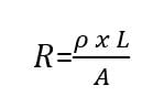
George Ohm studied the relationship between resistance and the size of the material that was used to make the resistor. He proved that the resistance (R) of a material increases as its length increases. This means that the longer and thinner wires offer more resistance. On the other hand, resistance decreases as the thickness of wires increases. Having said that, Georg Ohm came up with an equation that explains this relationship, where ρ = resistivity (Ω-m)
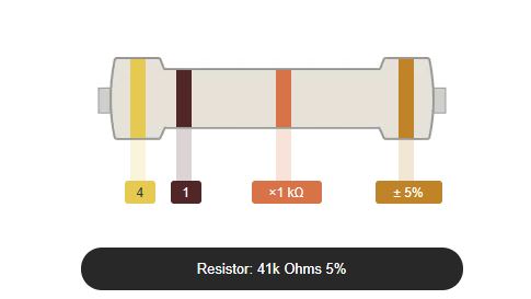
For a four-band color coded resistor, the 1st and 2nd band represent the 1st and 2nd significant digit while the 3rd band represents the multiplier, and the 4th band represents the tolerance.
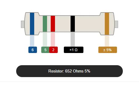
For a five-band color coded resistor (high precision resistor), the 1st, 2nd and 3rd band represent the 1st, 2nd and 3rd significant digit while the 4th band is the multiplier and the 5th band is the tolerance.
Resistor color coding table
For some four-band color coded resistor, another extra band (5th band) indicates the reliability in percent of failures per 1000 hours (1000h) of use.

Everytime a current passes through a resistor due to the presence of a voltage across, electrical energy is lost in the form of heat. The greater the current flow, the hotter the resistor will be. A resistor can be functional at any combination of voltage and current as long as it does not exceed the power rating that a resistor can convert into heat or absorb without any damage.
Resistor Power Rating is defined as the amount of heat a resistor can handle without sacrificing its performance in no definite time. In Ohm’s law, when a current flows through a resistance, a voltage is dropped across it producing a product that relates to power. In other words, if resistance is subjected to a voltage, or if it conducts a current, then it will always consume electrical power. Given this, we can say that these three quantities– power, voltage and current, are in a power triangle.
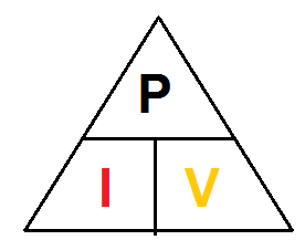
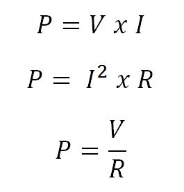
Using the Resistor Power Triangle is the best way to calculate the power dissipated in a resistor if we know the values of the voltage and current across it. Additionally, Ohms law allows us to calculate the power dissipation given the resistance value of the resistor. We can obtain two alternative variations of the above expression for the resistor power if we know the values of at least two among the three– voltage, current, and resistance.
Based on the power triangle, the electrical power dissipation of any resistor in a DC circuit can be calculated using one of the following three standard formulas, where V is the voltage across the resistor in Volts, I is current flowing through the resistor in Amperes, and R is the resistance of the resistor in Ohmss (Ω).
Example with LED
You can use blinking diode circuit.
In our circuit we have Arduino Uno R3 board with 5V, LED with 3V and 0.02A.
What will be the resistance of the resistor?
We use Omhs Law:
R = (VBattery - VLED) / ILED
R = (5-3)/0.02 = 100 ohms
Capacitor
A capacitor is a device that stores electrical energy in an electric field. It is a passive electronic component with two terminals.
The effect of a capacitor is known as capacitance. While some capacitance exists between any two electrical conductors in proximity in a circuit, a capacitor is a component designed to add capacitance to a circuit. The capacitor was originally known as a condenser or condensator. This name and its cognates are still widely used in many languages, but rarely in English, one notable exception being condenser microphones, also called capacitor microphones.