Drawing views
The view is a rectangular projection of the surface of the object facing the observer. 3 basic views are used in study drawings:
1) opposite view or main view;
2) top view;
3) left side view.
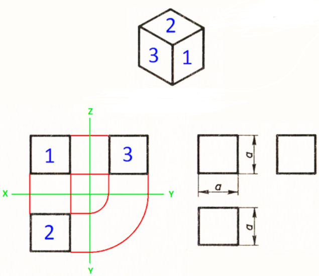
All views in the drawing must be placed in a certain relation. The top view should be below the front view, and the left side view should be to the right of the front view.
The front view or the main view should give the most complete picture of the shape and dimensions of the object.
The drawing of any object contains the contours of the visible and invisible surfaces. Visible lines are marked with a baseline, and invisible lines are marked with a dashed line. Symmetrical axes are marked for symmetrical parts.
Sequence of object view construction
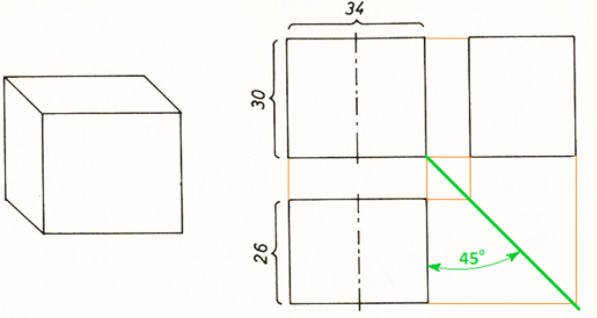
1. Before constructing a drawing, find out the geometric shape of the object. The given detail is a rectangular parallelepiped.

A rectangular parallelepiped appears as a rectangle in all three views and is easier to construct using a 450-angle auxiliary line.
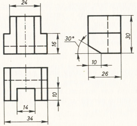
The length (34 mm) and height (30 mm) of the part are left in the front view. The length (34 mm) and width (26 mm) of the part are left in the top view. The height (30 mm) and width (26 mm) of the part are left in the left side view. All constructions are made with thin lines. As the front view and the top view are symmetrical, the axes of symmetry are drawn in them.
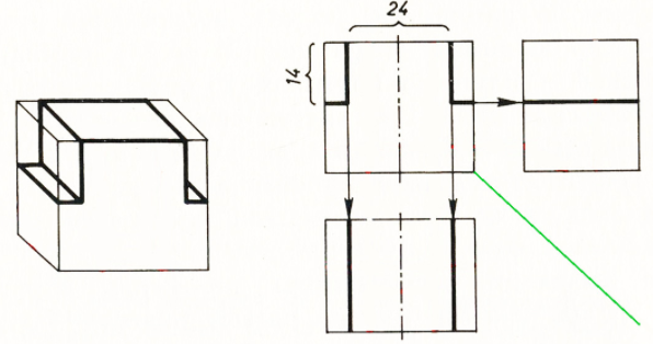
3. The next side cuts must be made. This is first done in front view, with 12 mm (24 mm in total) off both sides of the axis of symmetry. Draw vertical lines through the points obtained. Then draw horizontal lines in front view, 14 mm from the top line of the part. These incisions are also constructed in the other views.
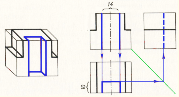
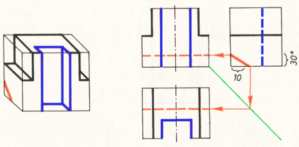
4. Now draw the front cut of the part. This is first done in front view, with 7 mm (14 mm in total) off both sides of the axis of symmetry. Draw vertical lines (in blue in the figure) through the points obtained. In plan view, 10 mm from the lower line of the part, 10 mm is left and a horizontal line is drawn intersecting the previously drawn vertical lines. This incision is then also constructed in the left side view, where it is represented as a dashed line due to the invisible contour.
5. As the last section of the rear section of the race. In the left side view, 10 mm is left on the bottom line of the part and a line is drawn at an angle of 300 (red in the figure). This section of the part is also constructed in the other views, where it is represented as a dashed line due to the invisible contour.
6. Insert the dimensions
 .
.
Last modified: Sunday, 1 August 2021, 7:01 PM