Potentiometers
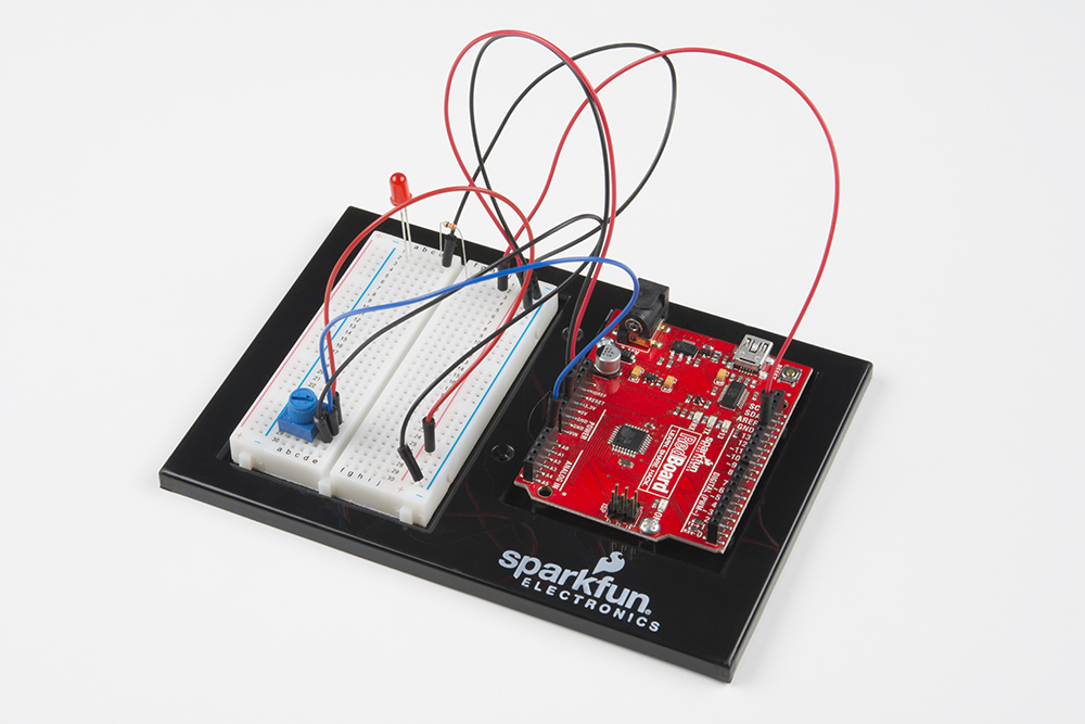
Circuit 1B: Potentiometer
Potentiometers (also known as “pots” or “knobs”) are one of the basic inputs for electronics devices. By tracking the position of the knob with your RedBoard, you can make volume controls, speed controls, angle sensors and a ton of other useful inputs for your projects. In this circuit, you'll use a potentiometer as an input device to control the speed at which your LED blinks.
Parts Needed
Grab the following quantities of each part listed to build this circuit:

New Components
Potentiometer
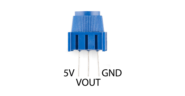
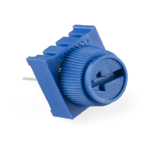
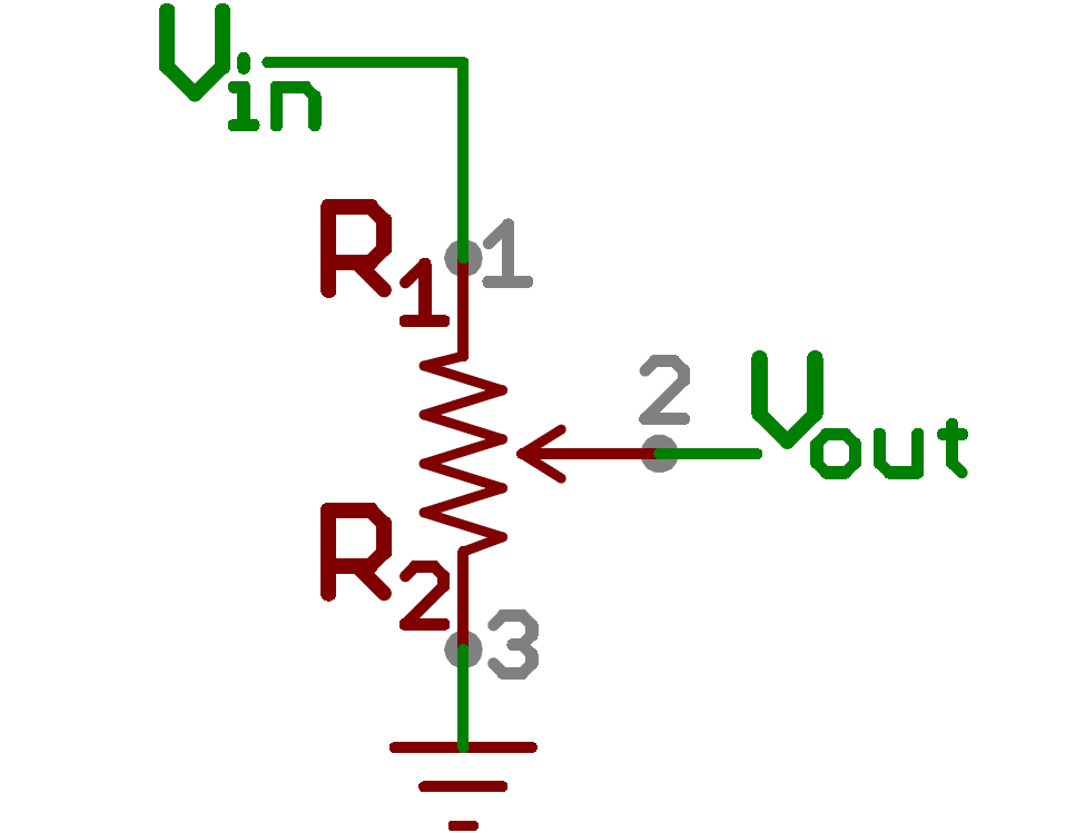
A potentiometer (trimpot for short) is a variable resistor. When powered with 5V, the middle pin outputs a voltage between 0V and 5V, depending on the position of the knob on the potentiometer. Internal to the trimpot is a single resistor and a wiper, which cuts the resistor in two and moves to adjust the ratio between both halves. Externally, there are usually three pins: two pins connect to each end of the resistor, while the third connects to the pot's wiper.
New Concepts
Analog vs. Digital
Understanding the difference between analog and digital is a fundamental concept in electronics.
We live in an analog world. There is an infinite number of colors to paint an object (even if the difference is indiscernible to our eye), an infinite number of tones we can hear, and an infinite number of smells we can smell. The common theme among all of these analog signals is their infinite possibilities.
Digital signals deal in the realm of the discrete or finite, meaning there is a limited set of values they can be. The LED from the previous circuit had only two states it could exist in, ON or OFF, when connected to a Digital Output.
Analog Inputs
So far, we've only dealt with outputs. The RedBoard also has inputs. Both inputs and outputs can be analog or digital. Based on our definition of analog and digital above, that means an analog input can sense a wide range of values versus a digital input, which can only sense two states.
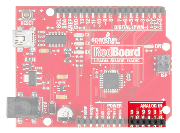
You may have noticed some pins labeled Digital and some labeled Analog In on your RedBoard. There are only six pins that function as analog inputs; they are labeled A0--A5.
Voltage Divider
A voltage divider is a simple circuit that turns some voltage into a smaller voltage using two resistors. The following is a schematic of the voltage divider circuit. Schematics are a universally agreed upon set of symbols that engineers use to represent electric circuits.
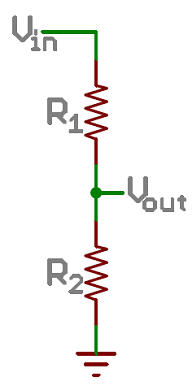
A potentiometer is a variable resistor that can be used to create an adjustable voltage divider.
If the outside pins connect to a voltage source (one to ground, the other to Vin), the output (Vout) at the middle pin will mimic a voltage divider. Turn the trimpot all the way in one direction, and the voltage may be zero; turned to the other side, the output voltage approaches the input. A wiper in the middle position means the output voltage will be half of the input.
Voltage dividers will be covered in more detail in the next circuit.
Hardware Hookup
The potentiometer has three legs. Pay close attention into which pins you're inserting it on the breadboard, as they will be hard to see once inserted.
Potentiometers are not polarized. You can attach either of the outside pins to 5V and the opposite to GND. However, the values you get out of the trimpot will change based on which pin is 5V and which is GND.