Practical Example. Toy hacking day
Objectives:
The goal in the context of the project is to summarize the knowledge and you have learned in recent days by applying to change a selected toy model by adding new features or changing some of them.
Example: To modify a toy (some old car) to car with RC (remote control), using Wi-Fi and mobile phone or computer, or to create a car with RC (remote control) from waste materials, using Wi-Fi and mobile phone or computer.
How to do it?
The instructor introduces the trainees to the material using a multimedia projector. With the help of the hardware components the circuit is built, the software is created in Arduino.IDE. It is uploaded to the controller and its operability is checked.


Circuito.io scheme.
The aim is to use the hardware components to build the practical scheme using the software for Arduino.IDE., to test the performance of the model and to create the modified toy.
Example
In our case, we have a toy, an off-road vehicle controlled by a remote radio frequency control. The idea is to start converting it into an intelligent car that is driven via the Internet. In the final stage of processing, it will be loaded with a camera through which we can see where it is moving and help control it from long distances, obstacle sensors and other additional extras.
At this stage, the first goal is to try to control it remotely over the internet.
When we talk about hacking children's toys, in which there is a built-in mechanism, as we saw in day 5 the approach is:
- To analyze the way the toy works.
- It is assessed what new functionalities we want to add or what we want to change in it.
- Analyze of the electronic, electrical and mechanical scheme.
- Assess which mechanisms can be used, which can be modified and what new ones to add.
- Design the new working scheme.
- Get the necessary components.
- Realizing the new idea.
This is the car in the beginning:
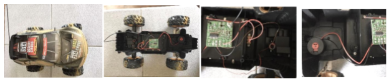
After the analysis of the construction, we see the following:
After inspecting the car device, we establish the following parameters:
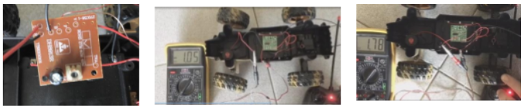
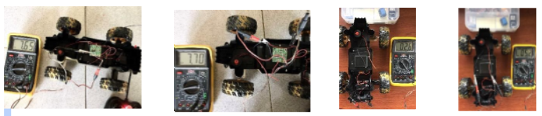
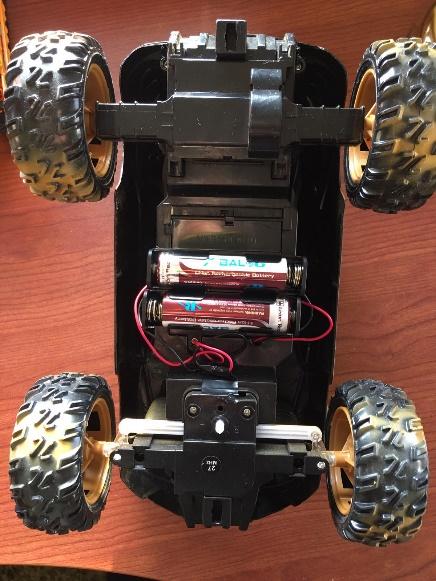
- It is powered by 4 AA batteries of 1.5 Volts. At idle, the total voltage of the batteries is about 7.7 volts, in working condition, about 6 volts with new batteries.
- It is controlled by two DC motors - one with a power of about 15 watts, and the other about 7 watts, one is for traction and the other is used to control the turn.
- The maximum current flowing through the electric motors is about 2 Amps.
- The car is controlled by a hybrid electronic circuit, which incorporates both radio frequency and power electronics and control.
- The radio control operates at a frequency of 27 MHz.
In this case, usually it is more economical to rewrite the control software than to download the old one, decompile it, modify and reload it. To do this, we can use a new microcontroller and additional components compatible with it.
Since we want the car to be controlled by a WEB-based application via the Internet, we choose the Arduinо.IDE compatible microcontroller ESP32. This microcontroller has a built-in WIFI module and is compatible with all sensors and accessories developed for the Arduino platform.
Parts Required
To complete this tutorial, we need the following parts:
- ESP32 DOIT DEVKIT V1 Board – read ESP32 Development Board
- L298N motor driver
- Power source: 4x 1.5 AA batteries or Bench power supply
- Jumper wires
- LED diodes x 4
- Resistor 1 Kohm x 4
- Solderless Board (half size).
Electrical scheme for example:

We will use L298N Motor Driver shield:
Let’s take a look at the L298N motor driver pinout and see how it works.

At the bottom you have a three terminal block with +12V, GND, and +5V. The +12V terminal block is used to power up the motors. The +5V terminal is used to power up the L298N chip. However, if the jumper is in place, the chip is powered using the motor’s power supply and you don’t need to supply 5V through the +5V terminal.
Note: if you supply more than 12V, you need to remove the jumper and supply 5V to the +5V terminal.
It’s important to note that despite the +12V terminal name, with the setup we’ll use here (with the jumper in place) you can supply any voltage between 6V and 12V. In this tutorial will be using 4 AA 1.5V batteries that combined output approximately 6V, but you can use any other suitable power supply. For example, you can use a bench power supply to test this tutorial.
In summary:
+12V: The +12V terminal is where you should connect your power supply
GND: power supply GND
+5V: provide 5V if jumper is removed. Acts as a 5V output if jumper is in place
Jumper: jumper in place – uses the motors power supply to power up the chip. Jumper removed: you need to provide 5V to the +5V terminal. If you supply more than 12V, you should remove the jumper
At the bottom right you have four input pins and two enable terminals. The input pins are used to control the direction of your DC motors, and the enable pins are used to control the speed of each motor.
IN1: Input 26 for Motor A
IN2: Input 27 for Motor A
IN3: Input 32 for Motor B
IN4: Input 33 for Motor B
EN1: Enable pin for Motor A
EN2: Enable pin for Motor B
There are jumper caps on the enable pins by default. You need to remove those jumper caps to control the speed of your motors.
Control DC motors with the L298N
Now that you’re familiar with the L298N Motor Driver, let’s see how to use it to control your DC motors.
Enable pins
The enable pins are like an ON and OFF switch for your motors. For example:
If you send a HIGH signal to the enable 1 pin, motor A is ready to be controlled and at the maximum speed;
If you send a LOW signal to the enable 1 pin, motor A turns off;
If you send a PWM signal, you can control the speed of the motor. The motor speed is proportional to the duty cycle. However, note that for small duty cycles, the motors might not spin, and make a continuous buzz sound.
SIGNAL ON THE ENABLE PIN MOTOR STATE
HIGH Motor enabled
LOW Motor not enabled
PWM Motor enabled: speed proportional to duty cycle
Input pins
The input pins control the direction the motors are spinning. Input 26 and input 27 control motor A, and input 32 and 33 control motor B.
If you apply LOW to input 26 and HIGH to input 27, the motor will spin forward;
If you apply power the other way around: HIGH to input 26 and LOW to input 27, the motor will rotate backwards. Motor B can be controlled using the same method but applying HIGH or LOW to input 32 and input 33.
Controlling 2 DC Motors – ideal to build our car for driving and control of turn by motor B.
If you want to build a car using 2 DC motors for the driving wheels, these should be rotating in specific directions to make the car go left, right, forward or backwards.
For example, if you want your car to move forward, both motors should be rotating forward. To make it go backwards, both should be rotating backwards.
To turn the robot in one direction, you need to spin the opposite motor faster. For example, to make the robot turn right, enable the motor at the left, and disable the motor at the right. The following table shows the input pins’ state combinations for the robot directions.
DIRECTION INPUT 26 INPUT 27 INPUT 32 INPUT 33
Forward 0 1 0 1
Backward 1 0 1 0
Right 0 1 0 0
Left 0 0 0 1
Stop 0 0 0 0
In our case, we will only use engine A to move. Engine B will be used to turn left or right, due to the specifics of the transmission mechanism.
DIRECTION INPUT 26 INPUT 27 INPUT 32 INPUT 33
Forward 1 0
Backward 0 1
Right 1 0
Left 0 1
Stop 0 0 0 0
Stop 1 1 1 1
Uploading code
The following code controls the speed and direction of the DC motor. This code is useful in the real world and is simple example to better understand how to control the speed and direction of a DC motor with the ESP32 in our case.


After the implementation of the example, it turned out that the voltage drop across the motor control integrated circuit is about 1.2 to 1.4 volts, and when starting the motors it reaches 2 volts. Therefore, it was necessary to increase the supply voltage in this case to 8.4 volts (preferably 9-10 volts) with sufficient power to run the car sustainably.