Blinking diode
Circuit with one diode
Create new circuit and call it "Blinking diode".
Add components:
- Arduino Uno R3 board
- Diode
- Resistor
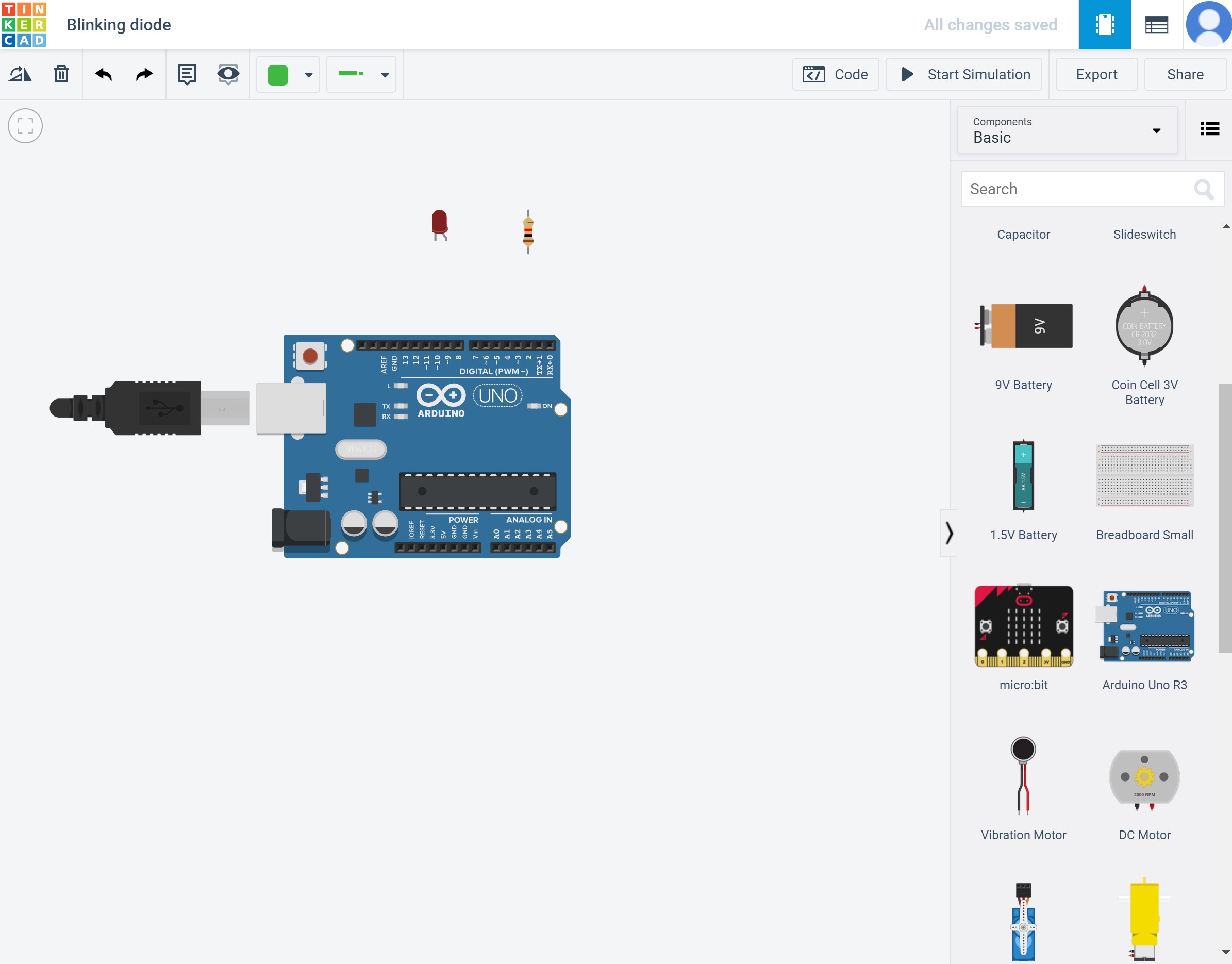
Lets understand what components we added.
Arduino Uno R3 is a microcontroller board based on the ATmega328P. It has 14 digital input/output pins (of which 6 can be used as PWM outputs), 6 analog inputs, a 16 MHz ceramic resonator (CSTCE16M0V53-R0), a USB connection, a power jack, an ICSP header and a reset button.
Light-emitting diode (LED) is a semiconductor light source that emits light when current flows through it.
Resistor is a passive two-terminal electrical component that implements electrical resistance as a circuit element. In electronic circuits, resistors are used to reduce current flow, adjust signal levels, to divide voltages, bias active elements, and terminate transmission lines, among other uses.
Connect components:
- Diode cathode connect to Arduino Uno R3 GND
- Diode anode connect to resistor
- Resistor connect to digital pin
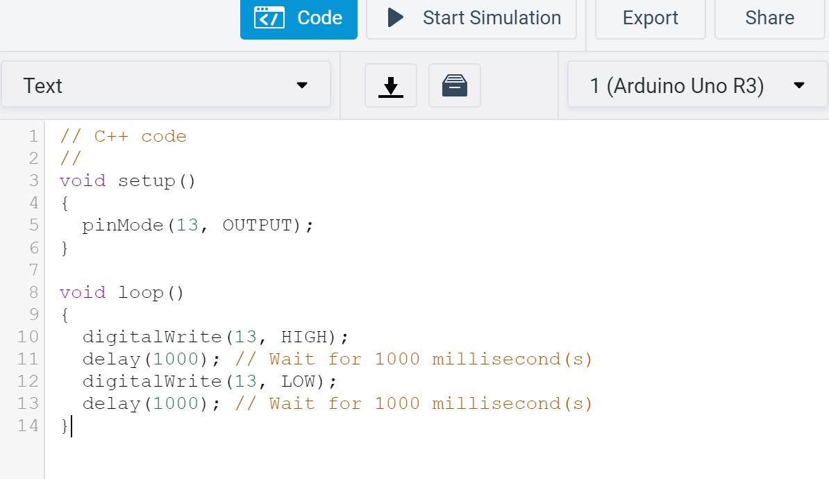
Default code:
Open Code section and choose text programming.
You see default code, let's take a look.
- Comment line (symbol // )
- Comment line
- Define function "setup()"
- Open function "setup()"
- Define pin 13 as output
- Close function "setup()"
- Blank line
- Define function "loop()"
- Open function "loop()"
- Set pin 13 to high
- Delay 1000 miliseconds
- Set pin 13 to low
- Delay 1000 miliseconds
- Close function "loop()"
Start Simulation and look what happen.
You already have blinking diode!
It's an built in Arduino Uno R3 diode.
Adjust code:
Look at your circuit. Which pin do you connect to resistor? At our example it's digital pin 9.
Add line above function "setup()" - int Led = 9; . This line define your diodes pin. Change all 13 too Led and start simulation!

Feel free to add more diodes and adjust code!
You can change diodes colors and make you own pattern or disco party!