Hole function
The tools in the Design > Solid > Create panel let you create a simple, counterbore, or countersink drilled hole and add threads to cylindrical solid geometry in Fusion 360.
You can use the following commands to create holes and threads in a solid body:
- Hole

- Thread

You can specify:
- The placement and extents to locate a hole
- The hole type, tap type, drill point, depth, diameter, and angle settings to customize a hole
- The length, offset, type, size, designation, class, and size of a thread
- Whether threads are cosmetic or accurately modeled
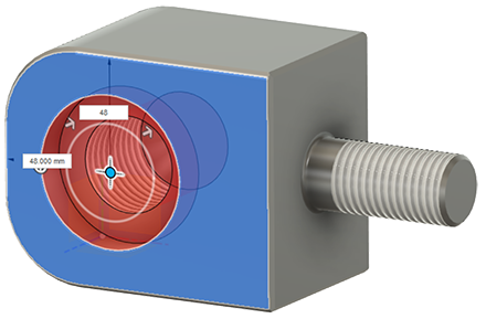
Hole
The Hole command defines a simple, counterbore, or countersink drilled hole in a solid body.
Thread
The Thread command adds internal or external threads to cylindrical solid geometry.
Click Design > Solid > Create > Hole
.The Hole dialog displays.
Select a Placement setting:
- At Point (Single Hole)
- From Sketch (Multiple Holes)
Select a face, plane, or sketch point to place the center of the Hole.
Adjust size, shape, and position settings as needed:
Drag the center point, edge, and depth manipulator handles to move and resize the hole after you place it, or enter exact values.
Select Reference geometry to define the size and depth of the hole by existing dimensions in your design.
Select one of the 3 Extents settings, and adjust its associated settings:
- Distance
- To
- All
Click Flip Direction to flip the direction of the hole.
Select a Hole Type, and adjust its associated settings:
- Simple
- Counterbore
- Countersink
Select a Hole Tap Type:
- Simple
- Clearance
- Tapped
- Thread Type
- Size
- Design
- Check the Modeled checkbox to preview the thread.
- Taper Tapped (Only available for Simple and Countersink hole types.)
- Thread Type
- Size
- Design
Select a Drill Point:
- Flat
- Angle
Tip: Use the dimension and settings preview in the Hole dialog to fine tune your settings.
In the Objects to Cut section, check or uncheck objects.
Click OK.
The hole displays in the solid body in the canvas.
Use the Thread command to add real or cosmetic threads to your design.
The Thread tool creates a thread on a cylindrical feature. The Repeat Thread option applies settings for the Hole to the cylinder. Cosmetic threads apply the appearance of threads to the selected geometry. Modeled threads are cut into the selected geometry.
- In the Design workspace, Solid tab, select Create > Thread and then select the face of the Hole.
- Use the manipulator to change the size of the Hole, if desired.
- In the Thread dialog, specify Thread Type, Size, and Class.
- Click Remember Size to remember these settings for the next thread feature you create.
- To apply the same settings to a cylinder, right-click, choose Repeat Thread, then select a cylinder.
- To add an offset and change the length, deselect Full Length, and use the manipulators.
- Select Modeled to show the thread as fully modeled. To revert to a cosmetic thread, use the Edit Thread dialog.